Introduction
This project was made over the course of 4 months as a part of the UBC UAS Design Team. The goal of the project was to build a rover that could autonomously navigate a course and deliver a water bottle to a specified location. The rover was built using a Teensy 4.0 microcontroller, a GPS module, an IMU, a motor driver, and an OLED display. The rover was programmed in C++ using the Arduino IDE.
Design
There are 4 main parts of the design that I would like to discuss:
- Structure and Mechanical Design
- Driving System
- Location and Navigation System
- Display System
Structure and Mechanical Design
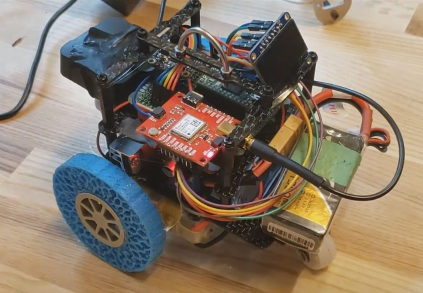
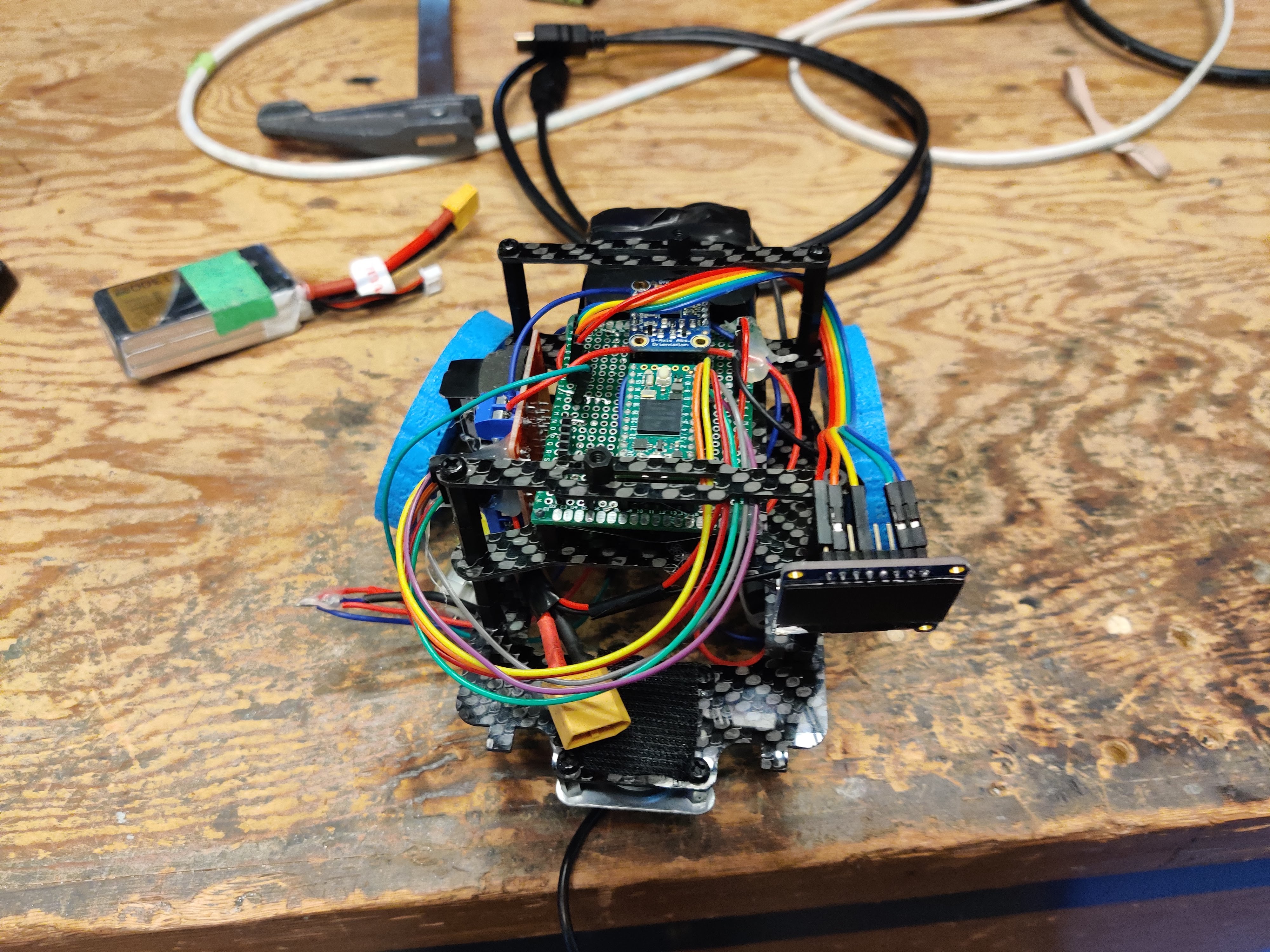
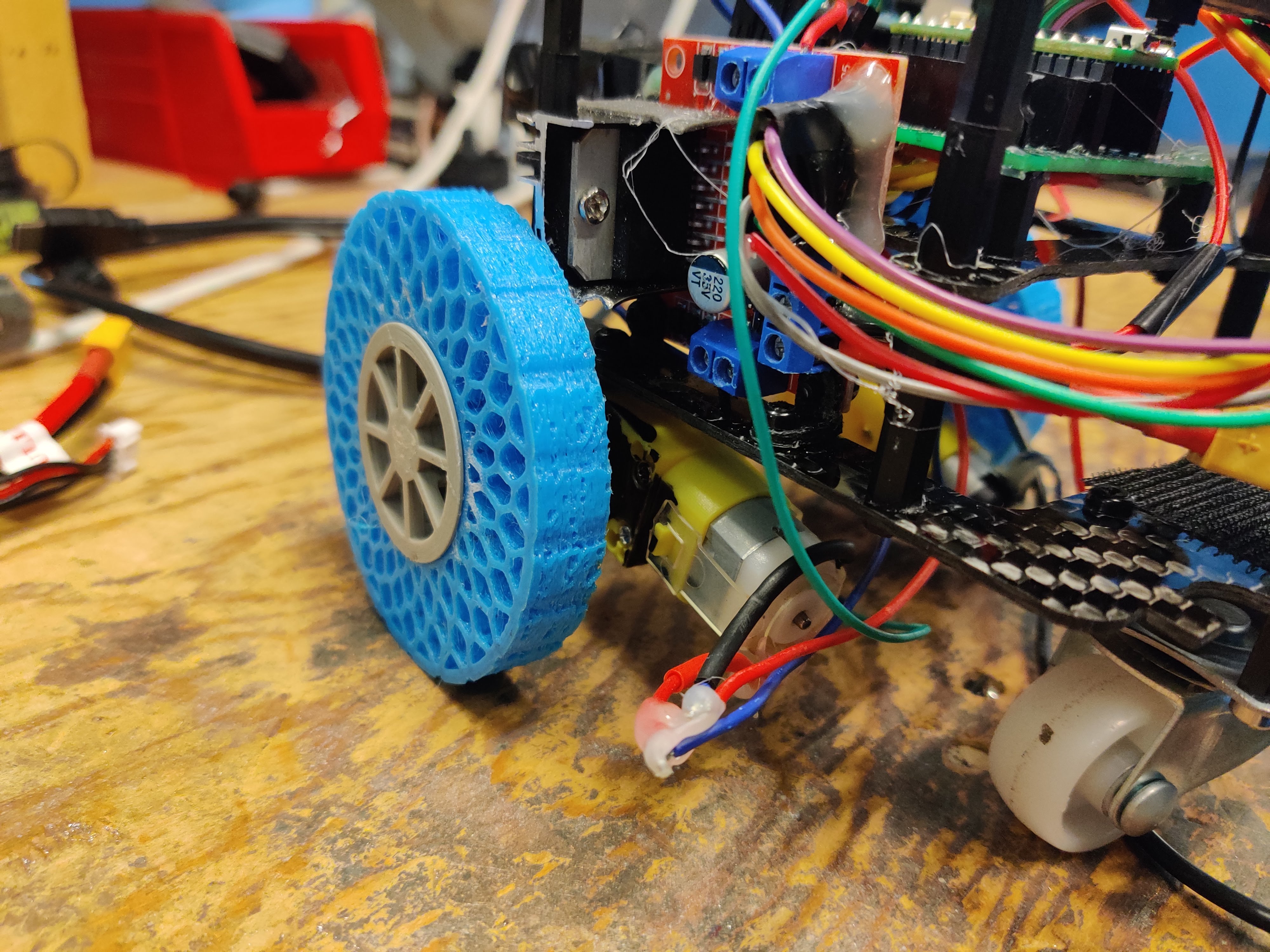
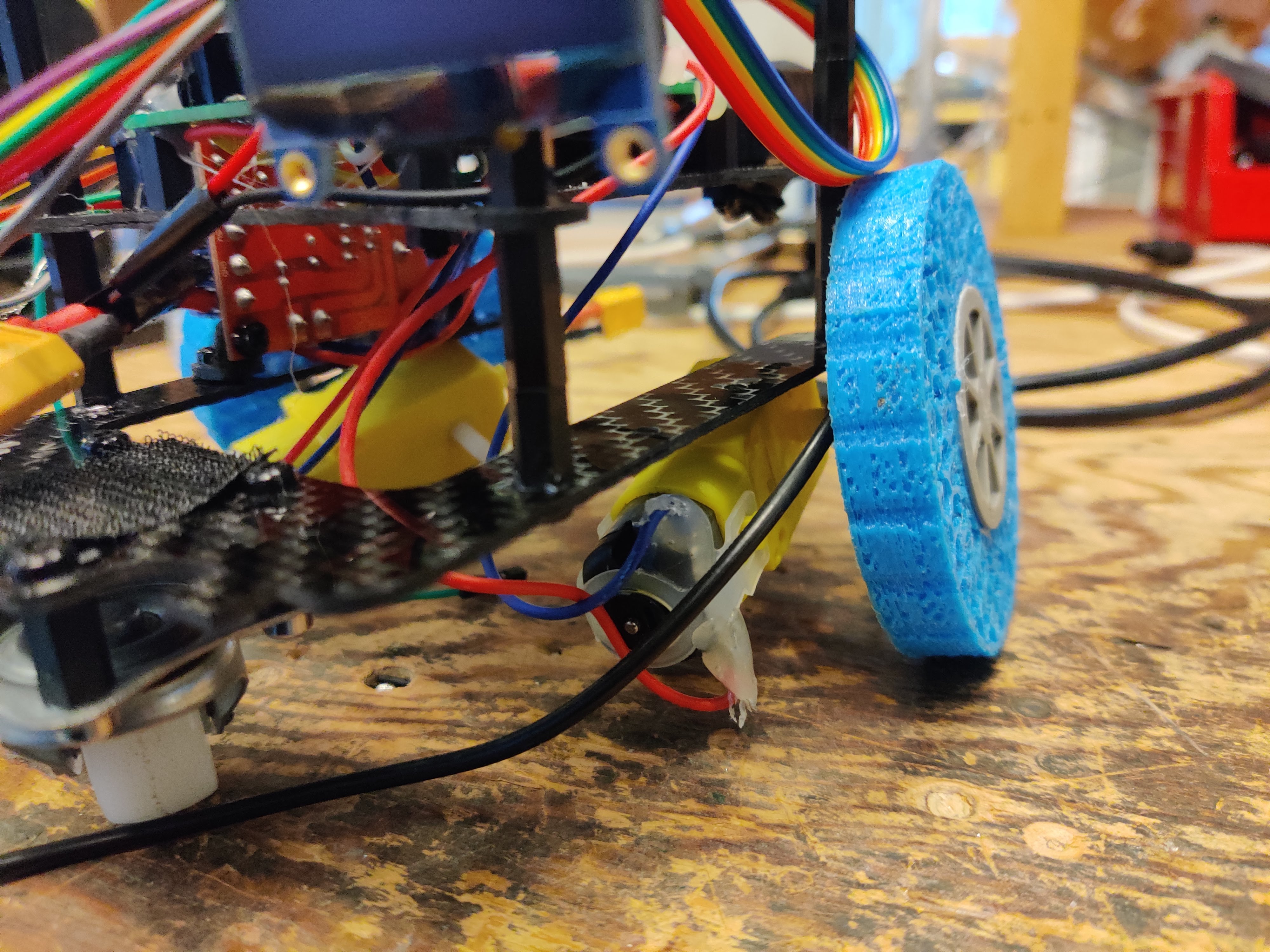
This was mostly done by UAS’s mechanical team. The rover’s chassis was made up of carbon fiber plates and standoffs. The rover’s wheels were 3D and were specifically designed to be squishy to dampen impact. This is because the rover was supposed to be deployed from a drone and would have to survive the impact of landing. Here are some images of the rover’s structure:
Driving System
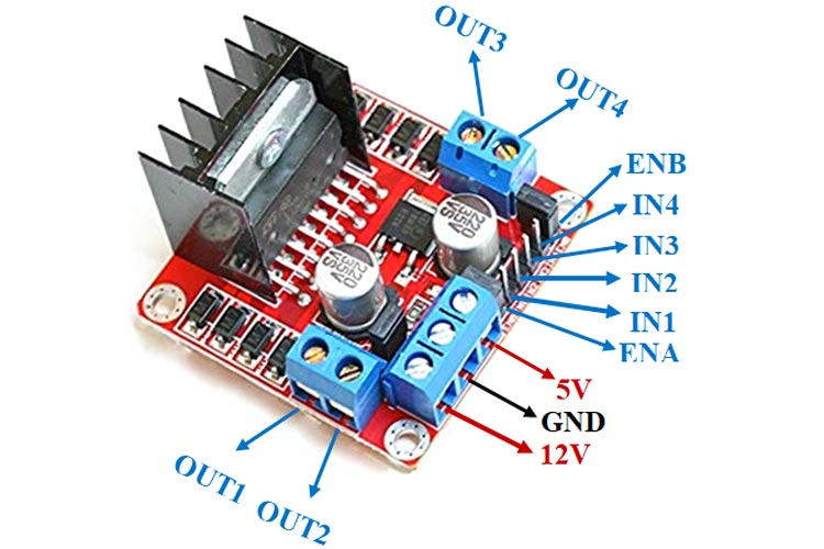
The Rover’s Driving system comprised of two DC motors and a motor driver. We used differental streering to control the rover. This means that one wheel on the left side of the rover is connected to one motor and one wheel on the right side of the rover is connected to another motor. This allows us to control the rover’s direction by varying the speed of the two motors. The motor driver we used was the L298N. This motor driver is capable of driving two DC motors at 2A continuous current per channel. The motor driver is controlled using PWM signals from the Teensy. Here is an image of the motor driver:
Location and Navigation System
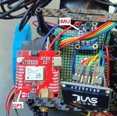
The rover’s location and navigation system comprised of a GPS module and an IMU. The GPS module we used was the SparkFun GPS Breakout - NEO-M9N. This GPS module is capable of outputting NMEA sentences at 10Hz. The GPS module was connected to the Teensy using a serial connection. The IMU we used was the Adafruit BNO055. This IMU is capable of outputting orientation data at 100Hz. The IMU was connected to the Teensy using an I2C connection. Here is an image of the GPS module and the IMU:
The IMU was used to get the rover’s orientation and the GPS module was used to get the rover’s location. The rover’s orientation was used to control the rover’s direction and the rover’s location was used to navigate the rover to the specified location. We employed a PID control loop to steer the rover autonomously. The control variable was the heading of the rover and the setpoint was the heading to the specified location. The PID control loop was implemented using a in house PID library that I wrote.
Apart from steering, the IMU had one more very important function. It was used to detect when the rover has landed on ground. The rover was lowered from the drone using a automatic winch. Once the rover landed on the ground, it had to automatically start its mission. So, we needed the IMU’s accelerometer to detect the landing.
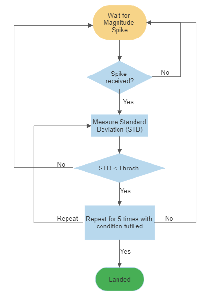
The landing detection algorithm was using the total X, Y and Z axis acceleration and computing the total acceleration using the following formula:

Once the magnitude was higher than a certain threshold it would mean then there was some kind of impact. tHis could be due to rover landing or wind that made the rover swing while being deployed or something hit the rover while it was being deployed. So we neede to be certain that the rover has actually landed. So we used one more step.
After the initial spike, we would sample this magnitude for a small window and compute the standard deviation of the samples. If the standard deviation was below a certain threshold, we would assume that the rover has landed. This would help us differentiate between the rover landing and the rover swinging due to wind. If the rover was still moving, the standard deviation would be high but if the rover was completly stationary, the standard deviation would be low. Thus, using this algorithm, we were able to detect when the rover landed. Below is a logic diagram of the algorithm:
Display System
The display system was used as a debugging tool. It was used to display the rover’s current location, the rover’s heading, the rover’s setpoint, and the rover’s current state. The display system comprised of a 128x64 OLED display. The display was connected to the Teensy using an I2C connection. Here is an gif of the display:
Here is a Demo of the rover in action:
This video demonstrates the rovers ability to go towards a particular direction. Which it does correctly. The steering PID was not perfectly tuned. As seen by the oscillations in the rovers movement.