Introduction
This project was made over the course of 8 months as a part of the UBC UAS Design Team. The goal of the project was to build a GPS Guided Parachute that could autonomously navigate a course and deliver a water bottle to a specified location. The system was built using an ESP32 microcontroller, and position sensors such as GPS, IMU and Barometer. The system was programmed in C++ using the Arduino IDE. The code for the system can be found on our GitHub Repository
Design
There are 4 main parts of the design that I would like to discuss:
- Structure and Mechanical Design
- Hardware Design
- Software Design
- Localization and Telemetry Design
- Navigation System
Structure and Mechanical Design
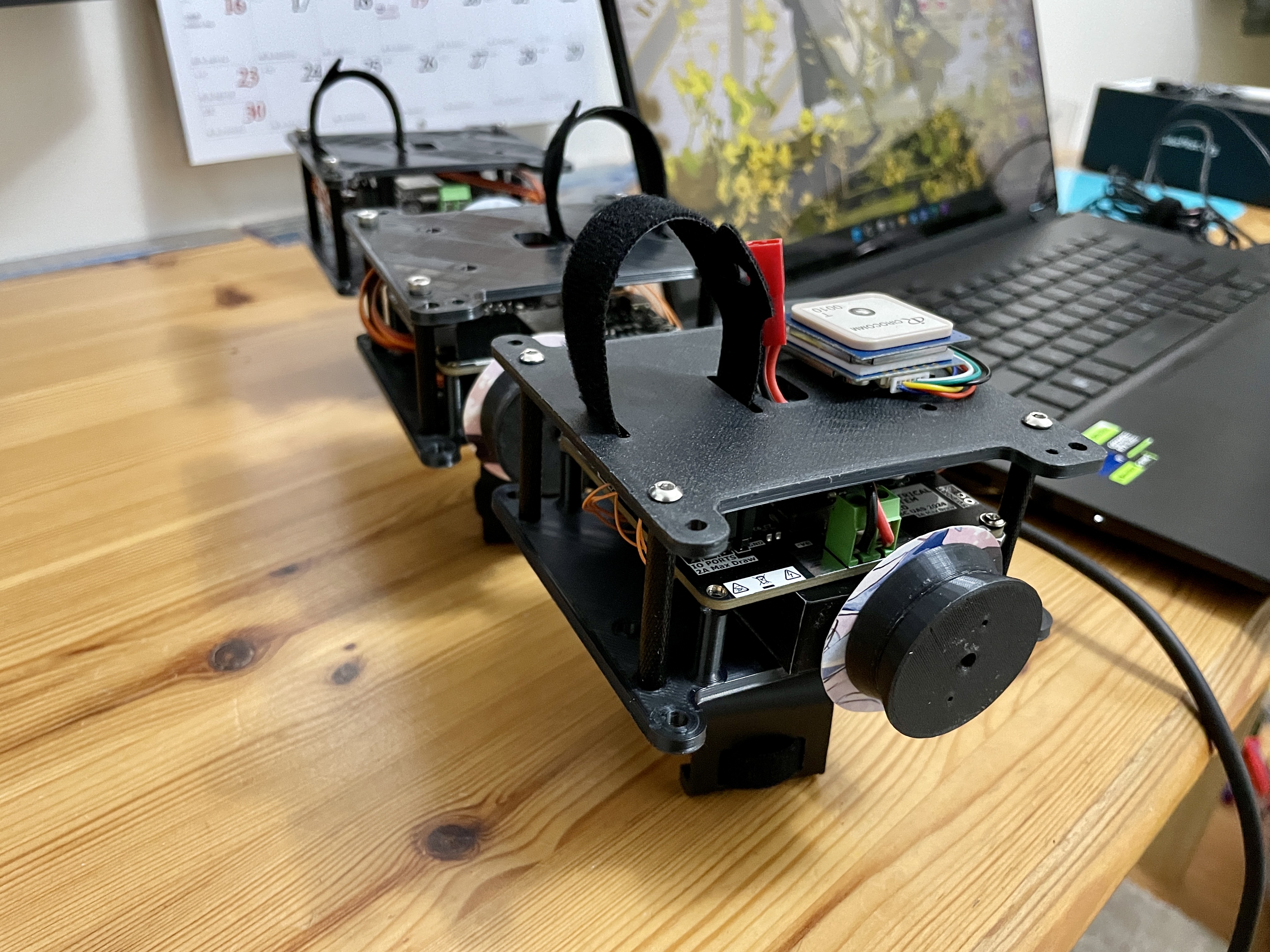
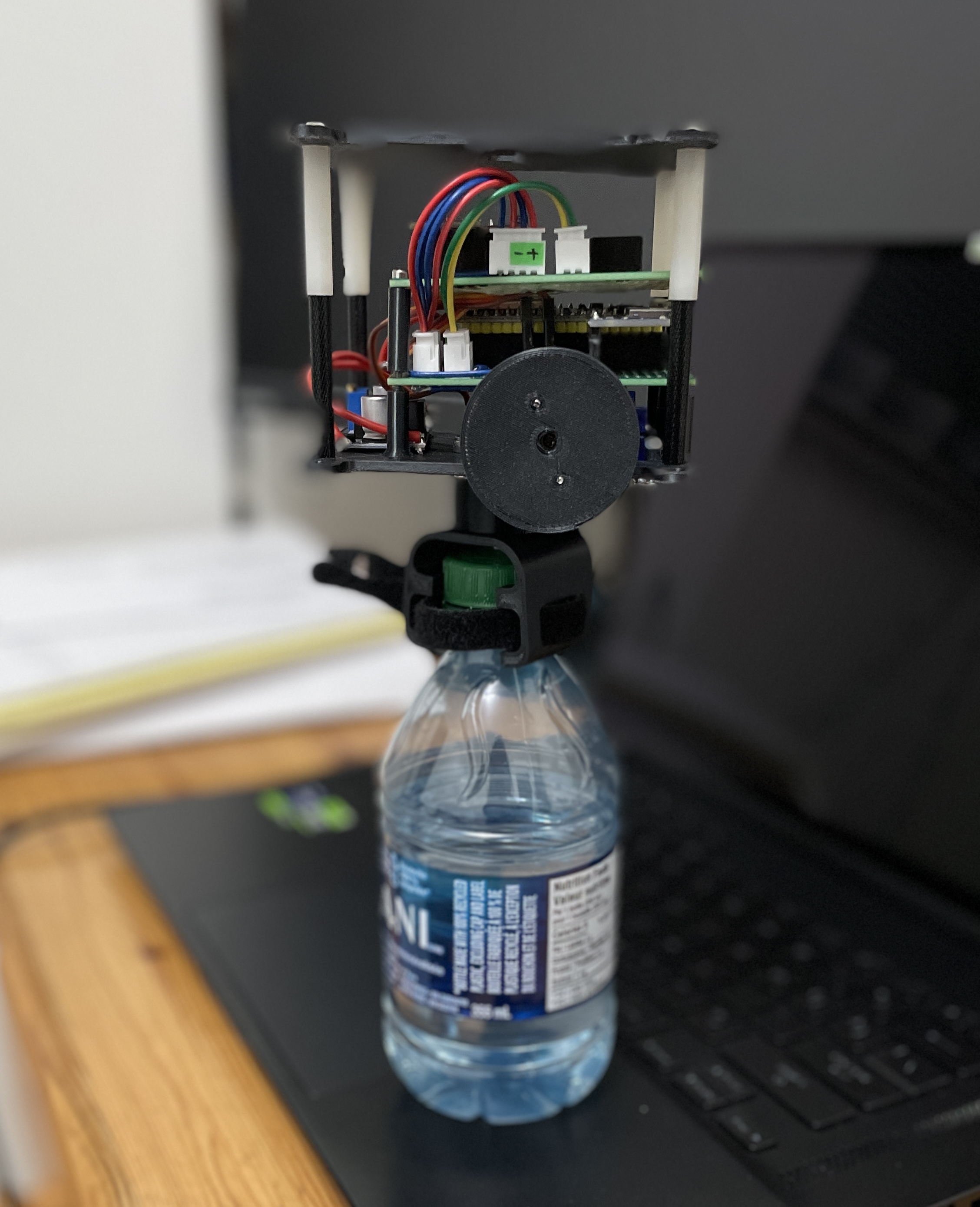
This was mostly done by mechanical team. The parachute was hand sewn with cloth and the base plate and supports were 3D printed. I had very little role in this part fo the project. The team ran parachute simulation and drop tests to correctly choose the design parameters. Here is an image of the payload’s structure and a gif of some simulations the team ran:
Hardware Design
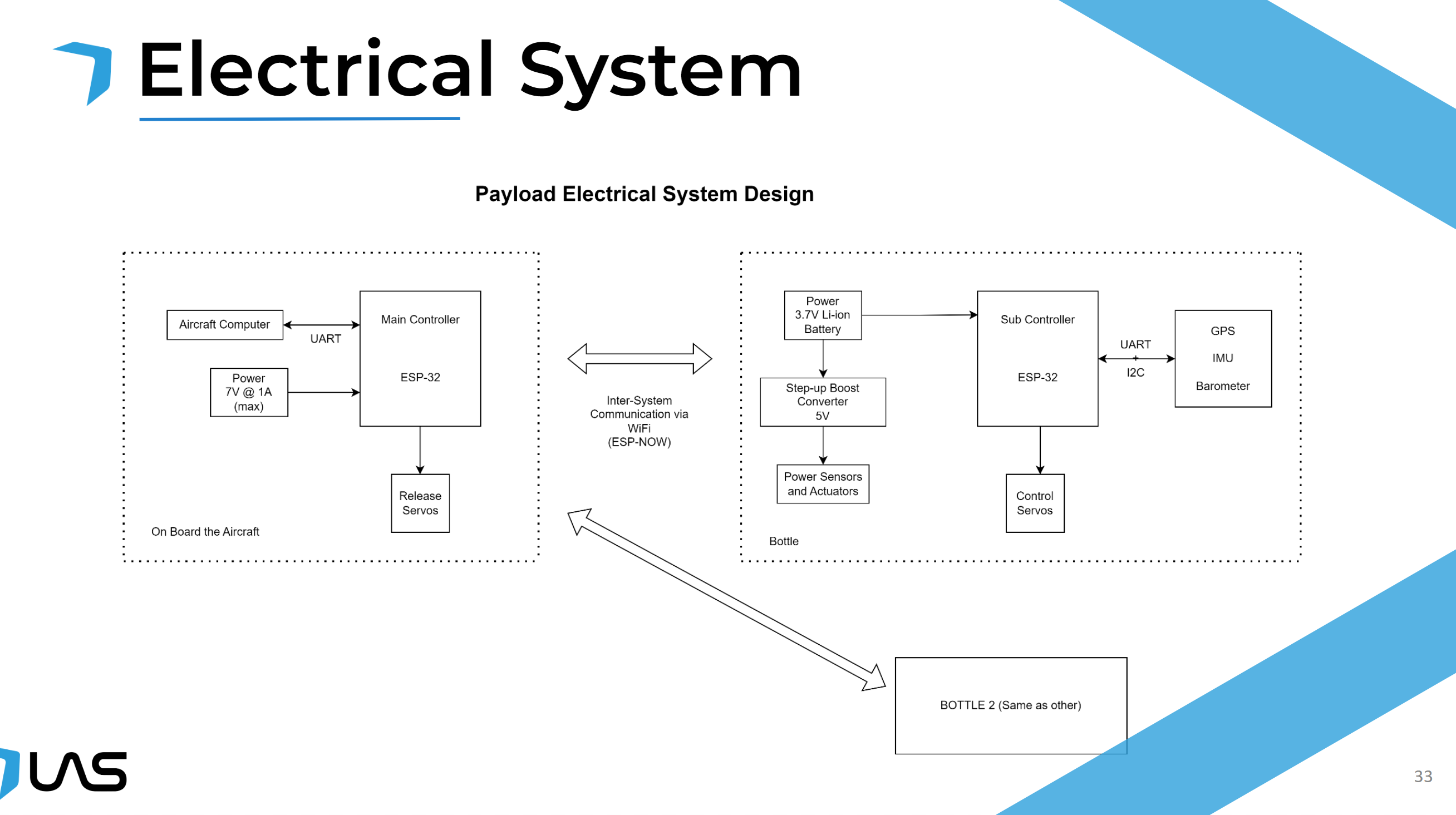
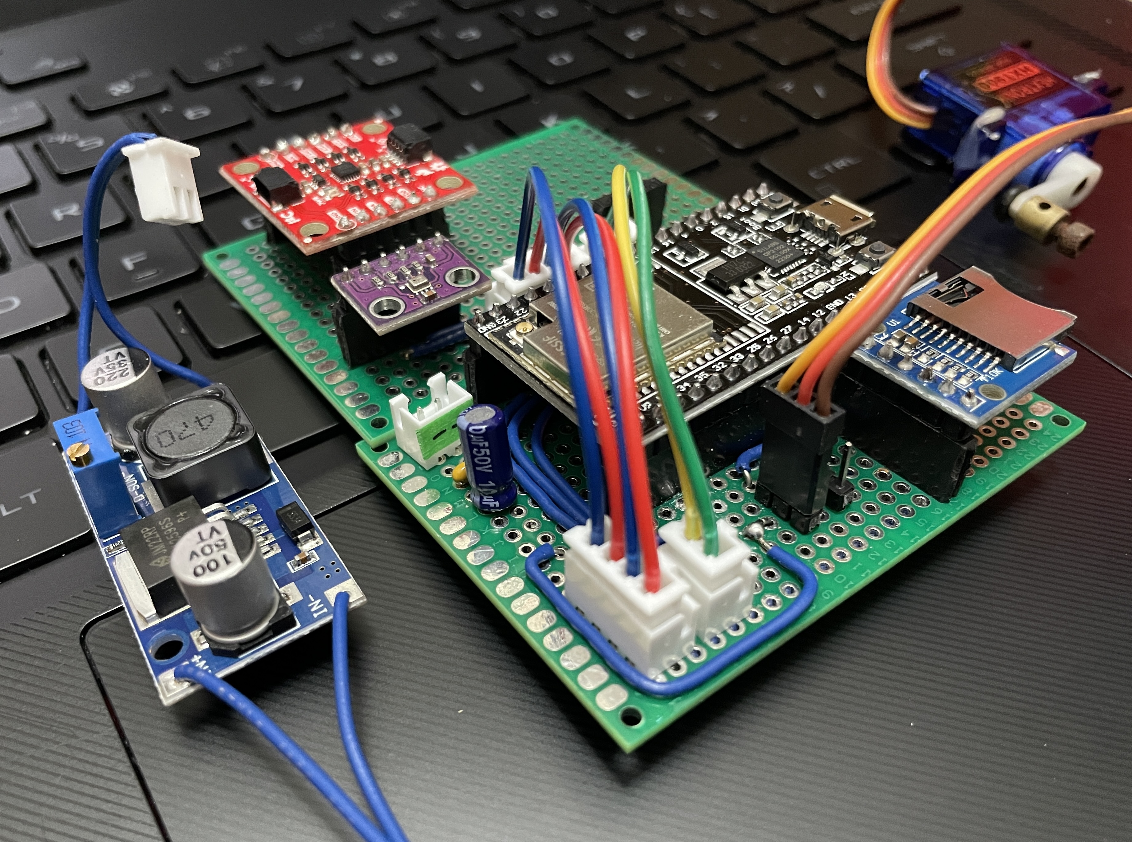
The system contains three major sub sections: Power distribution system, micro-controller circuitry and all the sensors/peripherals attached. Since the system was to be gliding in air, we definitley needed battery power. I decided to chosse a 2 cell, 7.4V li-po battery as they have good energy density and are sufficiently light and small to be easily cairred by the drone that drops the parachute. Below is a high level diagram of the system, ignore the 3.7V battery, we upgraded to 7.4V and used a Buck converter
Power Distribution System
This was essentially used to convert the 7.4V from lipo to 5V/3.3V to drive the servos, micro and all sensors. A buck converter was used to step down the voltage. The output was capable to driving 5V at 4A. We decied high current rating due to the servo motors.
Micro-controller System
For this project I decided to use an off the shelf ESP32 module, and used minimum components to get it wokring. I followed the Espressif’s documents about ESP32 hardware design. The reason to use this micro was due to its less cost and wireless capablity. The aircraft needed some communication channel to let the payload know the drop point and this was done right beofre the drop hence wireless comminucation hardware was beneficial for the system.
Sensors/Peripherals
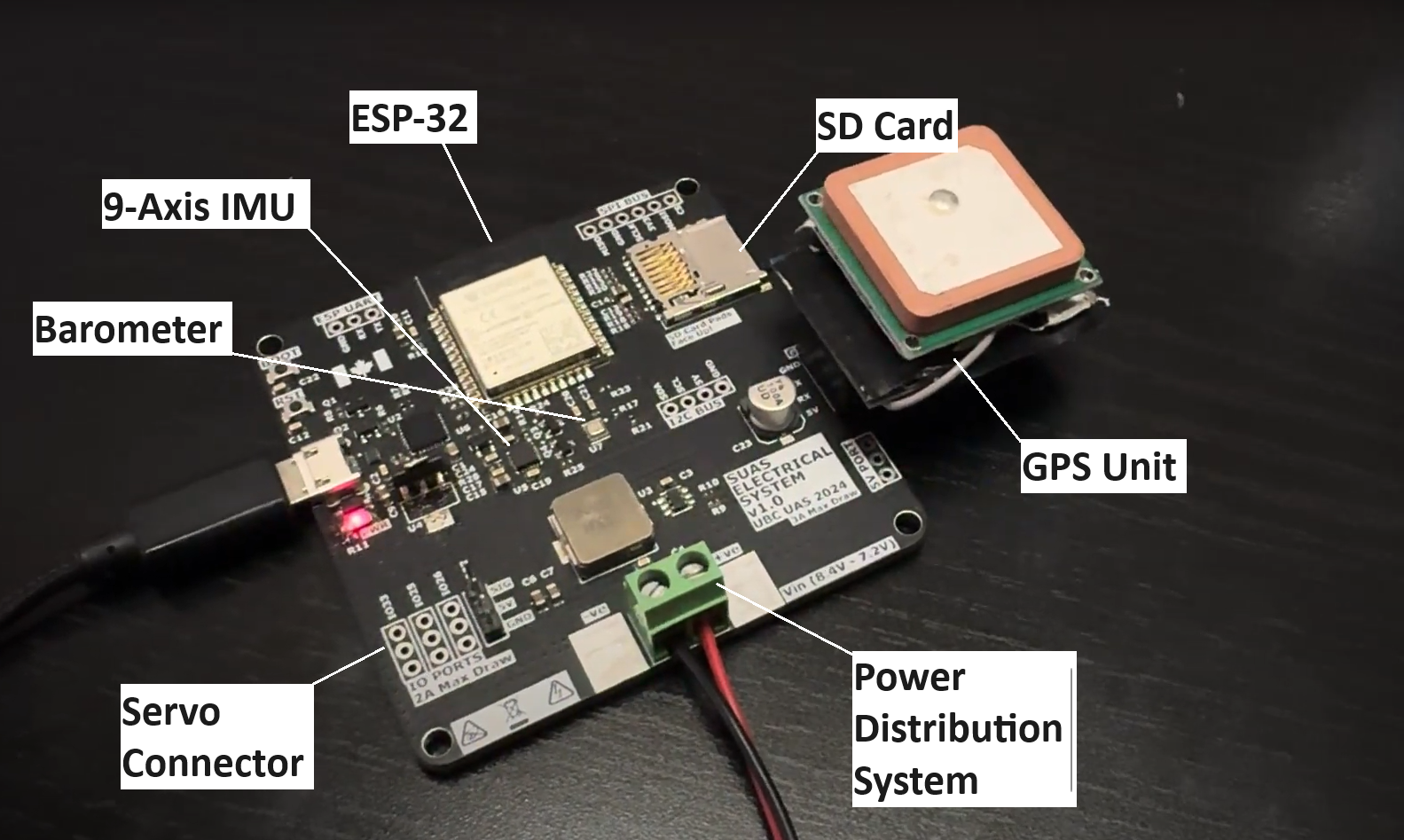
The system used a variety of sensors: 9axis IMU, Barometer, GPS (but only headers to connect an external module) and SD card socket to allow dynamic config and telemetry recording. There were also some headers to connect upto 4 servos.
I designed the complete PCB in Altium Designer and it was manufactured by PCBWay. Below is a comparision of the system prototype and finished design.
Software Design
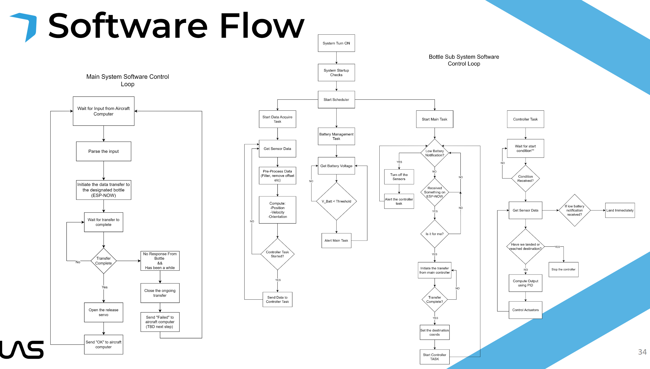
Since we are using ESP32, we have a variety of stuff at our disposal, better performance, lots of hardware peripherals, wireless communication and dual cores. Our idea was to run a couple of tasks in parallel each doing one part of the system. The communication task would get the GPS co-ordinates from the aircraft, the sensor data acquisation task reads and processes data from the sensors, battery management task records the battery voltage and the steering task to control the trajectory of the parachute. Below is our software flow diagram:
Localization and Telemetry Design
This part describes how the data from various sensor was acquired and then further processed to get a precise estimate of the parachtue’s real time 3d position and orientation. But before I discuss the design it might be beneficial to understand why we even need extra processing.
Need for speed sensor processing
For the flight controller’s navigation system, we simply need the GPS position and the Yaw angle to direct the parachute to the desired location. We can compute the desired yaw from two sets of GPS coordinates and design a control system to make the curent yaw match the desired yaw.
So we just need a compass and a GPS modules, then why go for a fancy setup?
The answer is how fast we need our data. Most hobby grade (and cheap) GPS modules output at a rate of 1-10Hz max. This rate is very less for our application and there are a lot of dynamic factors that can suddenly alter the parachute trajectory; wind being a prime example. So another approact to get super fast position would be to double integrate the X,Y,Z acceleration obtained from IMU to get position. This way we can keep track of how much we moved. Most cheap accelerometer/IMUs output at 1KHz which is very good for our system. However, are we forgeting about something?
Well Yes, its NOISE. If you have ever worked with an accelerometer before you must have encounted the random noise in the output signal. If we integrate the signal with the noise then output gets more and more imprecise overtime as that noise get accumulated.
So how do we get a fast and noise free position signal?
ENTER: KALMAN FILTERING
This is a signal processing algorithm that is used to combine two set of signal describing same value and then produce a better more reliable estimate of the actual value. I am not an expert in statistical analysis but rather a highly motivated engineer, so my explantions might not be 100% mathematically correct. However if you’d like to dvelve deeping into Kalman Filtering then this Wikipedia Article might be a good starting point.
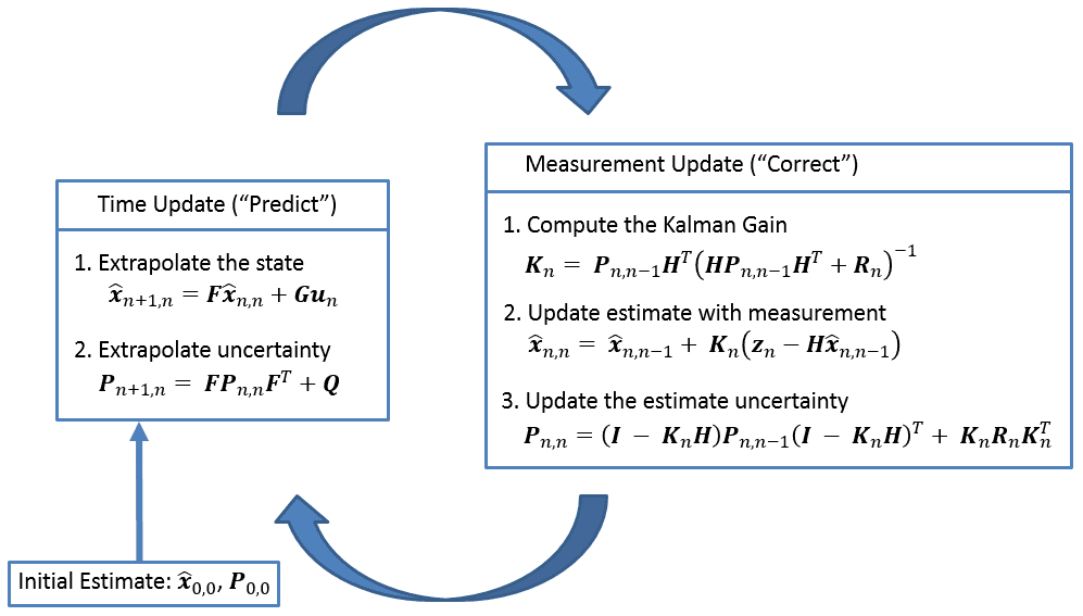
Now I will briefly walk through our justification and implementation of the algorithm. As we know we have two sources of measurment: GPS (slow but low noise) and IMU (fast but high noise). Kalman Filtering combines these two sets of measurment to produce a new estimate of our current postion which is both fast and low in noise (to an extent). There are two high level steps in the algorithm. Predict and Update. In the predict stage, we use the current estimate of our position and combine it with new incoming data from the IMU, so this step happens at a faster rate. In the update step we correct for any noise/drift in our estimate by using the new value from the GPS. So this step is slower. There are a variety of parameters that needs to be provided for the mathematical system to produce reliable and accurate estimations such as noise levels, sample rate, standard deviationn in the sensor values.
The implementations consists of a variety of mathematical operations corresponding to the predict and update steps that are well defined in textbooks. The challenging part is to make the calculation computer friendly by this I mean if we can, then optimize out or bundle together matrix multiplications and inverse calcualtions to make them run faster. There was also a design phase where I collected raw data from the system and used MATLAB to simulate our Kalman Filter with different parameters. The final implemantation was a highly flexible Kalman filter class which would allow us to reuse the filter for different systems in the future.
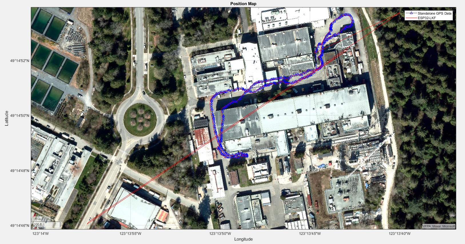
Here I have a plot of the comparision of the filter performance. The output from the Kalman Filter was stored along with the raw GPS data and you can see that both traces are very close to each other, however the GPS trace has far fewer different points due to the slow output rate.
Here is some visualization I did while testing. The right feed is the realtime orientation and left feed is the 3D position. It is to be noted that the 3D position doesn’t work well for distances less than 5m as thats the minimum resolution of the GPS.
Navigation System
The navigation system’s sole purpose is to get the position from the Localization System and control the servos to maintan the correct path towards the desitnation. We utilized a PID controller to make sure that the current yaw of the parachute would match the desired yaw. Due to time restrictions we were not able to implement any fancy path planning algorithm. Our approach was a simple two point navigation. You get the desired yaw from two GPS coordinates and match it. It worked effectively for our system. However, in future we would surely want to dive deeper and explore more efficient path planning algorithms.
Here is a Demo of the parachute in action:
In the video the payload was dropped from around 75feet. The parachute landed at the correct position.