In third year at UBC (Jan-Apr 2022), a group of three (Jonathan Zhang, Nico Zhu and me) took on ELEC 391: a capstone style course where the objective was to design and simulate a fully functional robot arm. Our reference model was the Yamaha YK350XG, a commercial SCARA (Selective Compliance Articulated Robot Arm) used in industrial pick and place applications. We designed the robot entirely from scratch: the mechanical assembly in SolidWorks, the electronics in Altium Designer, and the control system in MATLAB and Simulink. The project culminated in a complete cosimulation where the robot traced paths and responded to PID controllers in real time.
The robot has 4 degrees of freedom: XY planar motion through two arm joints (shoulder and elbow), Z axis motion via a linear actuator, and yaw rotation at the end effector. The end effector uses a vacuum mechanism to pick up objects.
Mechanical Design
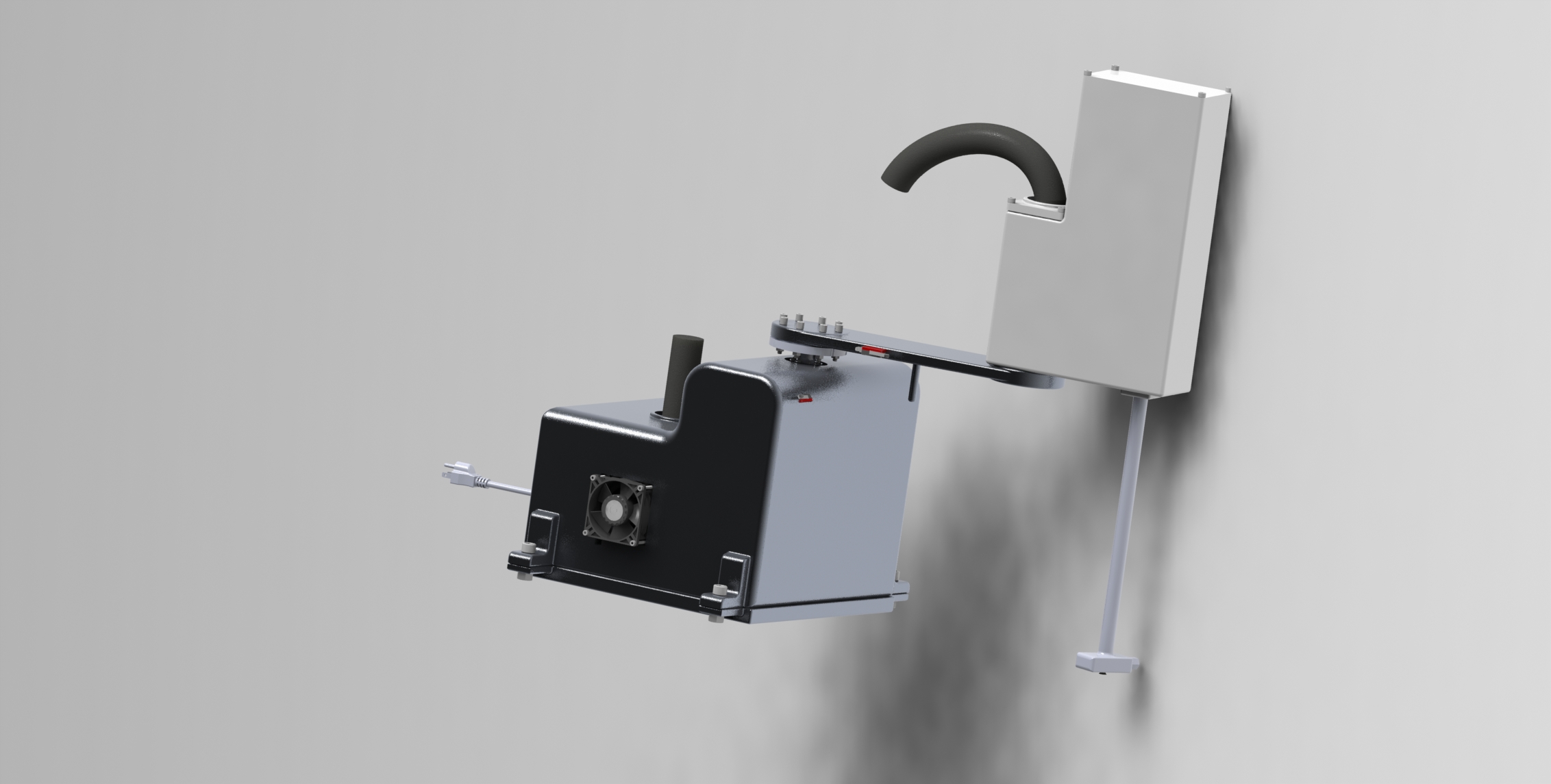
The robot consists of three main structural components: the base, the upper arm, and the forearm, plus an end effector assembly at the tip.
Upper Arm
- Length: 300mm (center to center)
- Material: Aluminium Alloy 3003
- Weight: ~1730g
- Connects the shoulder (base) joint to the elbow joint
- Features a 70mm mechanical stopper and a shaft extender at the elbow end
Forearm
- Length: 150mm
- Material: ABS Plastic (chosen for its strength to weight ratio; aluminium was too heavy for the elbow motor to drive effectively)
- Weight: ~3765g (including the enclosure that houses the end effector motors)
- Contains a built in enclosure for routing wires and mounting additional motors
Base
- Dimensions: 350mm x 350mm footprint, 300mm tall
- Houses all the power electronics: transformer, capacitor, power supply PCB, motherboard, and motor drivers
- Curved top to reduce material usage and improve aesthetics
End Effector
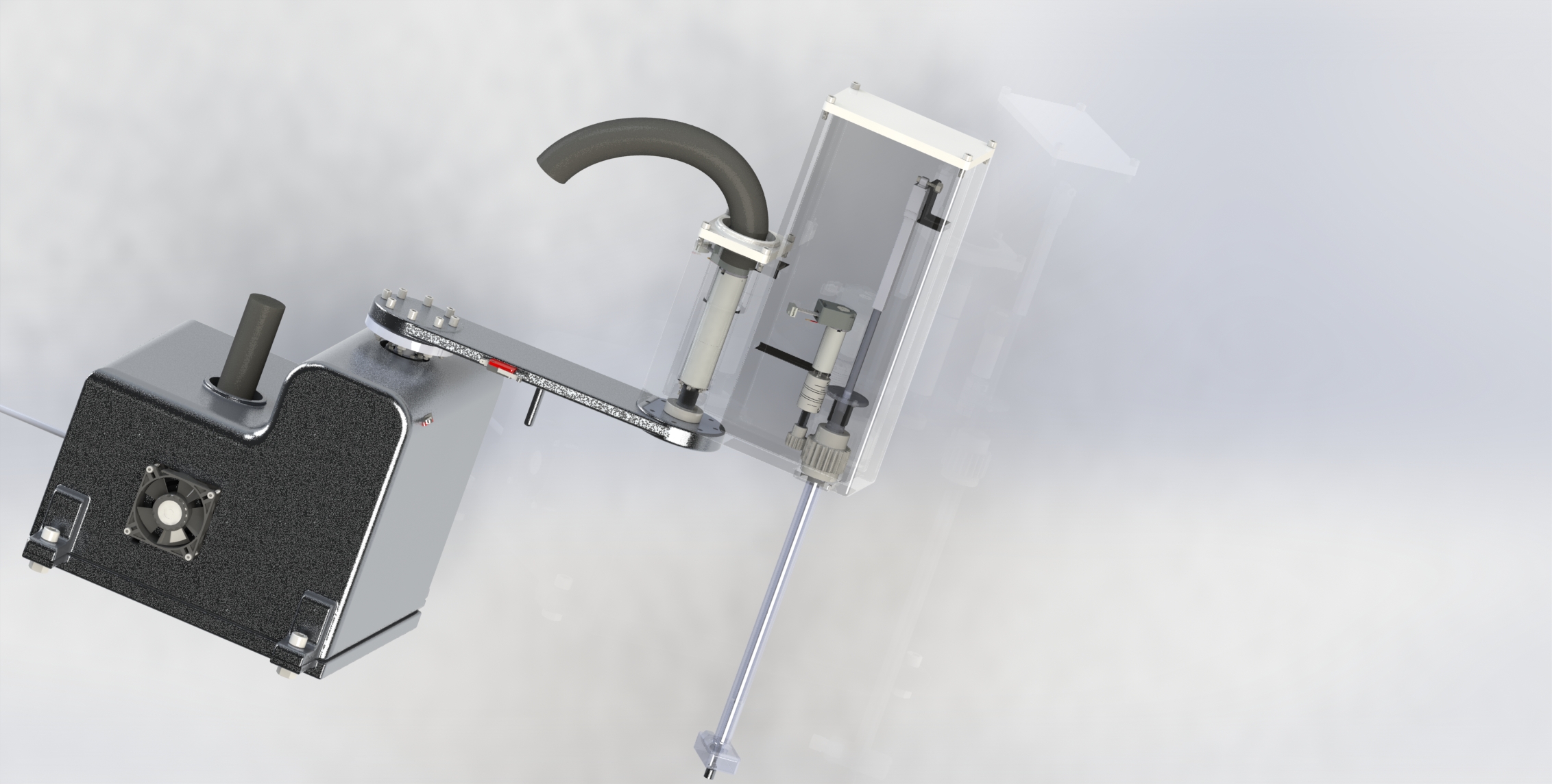
The end effector allows the robot to move payload up and down and rotate it. A linear actuator handles Z axis motion while a small DC motor controls yaw rotation. Objects attach to the end effector using a vacuum pickup mechanism with a one way valve.
Here is an exploded view of the complete assembly (160 total parts):
The total weight of the robot including all electronics and wiring came to 26 kg, well within the 35 kg requirement. Finite Element Analysis in SolidWorks confirmed that the upper arm deflects only 0.003mm under load and the forearm handles forces equivalent to ~60 kg, far exceeding the 2 kg payload requirement.
Electronics and Hardware
This was the part I was primarily responsible for. The electrical system consists of four custom PCBs, all designed in Altium Designer.
Power Supply
Converts 120V 60Hz AC wall power to 24V DC at 20A. Uses a Triad Magnetics F 1000U transformer rated at 504W, a full bridge rectifier (Vishay GBUE2560) and a 2200µF smoothing capacitor. A 5A fast acting fuse on the input side provides short circuit protection.
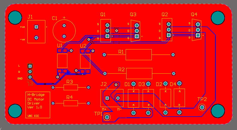
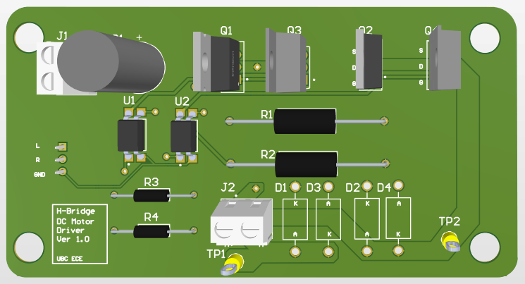
Motor Driver (H Bridge)
Custom H Bridge design using IRF540N (N Channel) and IRF5305 (P Channel) MOSFETs, rated for 24V at 8A continuous. Optocoupler isolation (Vishay VO615A) sits between the microcontroller and the power stage to protect the logic side. Each driver accepts Left/Right PWM signals for bidirectional motor control and has space reserved for heatsinks on the MOSFETs. Four of these boards were built, one for each motor.
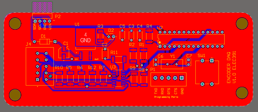
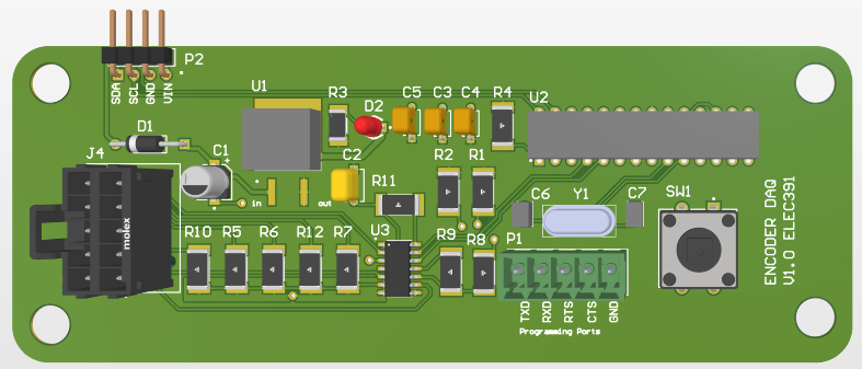
Encoder DAQ Board
Tracks motor position using Maxon 1024 count per turn optical encoders with quadrature output. An ATMEGA328P microcontroller on each board converts the quadrature pulses into an absolute angle and communicates it to the main controller over I2C (only 2 wires needed for all encoders on the bus). The boards also support homing calibration commands from the main controller. Four of these boards were built, one per motor.
Motherboard
The central hub connecting all subsystems to the main microcontroller. Hosts TXB0104 bidirectional voltage level shifters for 3.3V to 5V conversion (since the Teensy operates at 3.3V logic). Integrates connectors for 4 motors, 4 encoders, 3 limit switches, and 2 PWM controlled cooling fans. The board includes both 5V and 12V linear regulators for powering peripherals.
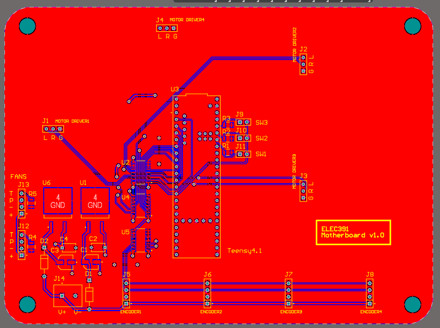
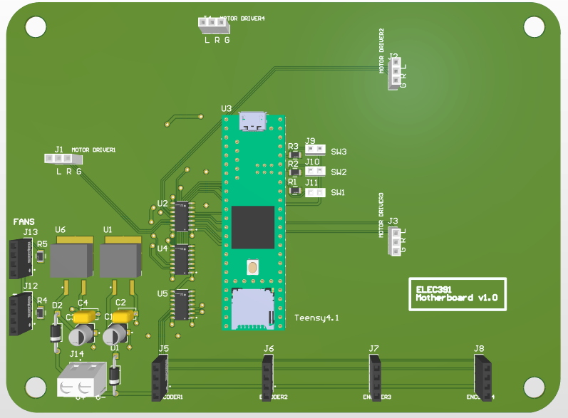
Main Microcontroller
We selected the Teensy 4.1 (ARM Cortex M7 at 600MHz) for its speed, large number of IO pins (55 digital, 35 PWM), and ample flash memory (7936 KB). The control loop runs at 1000 Hz, and the Teensy handles PID computation, path planning, kinematics, I2C communication, and motor PWM output simultaneously.
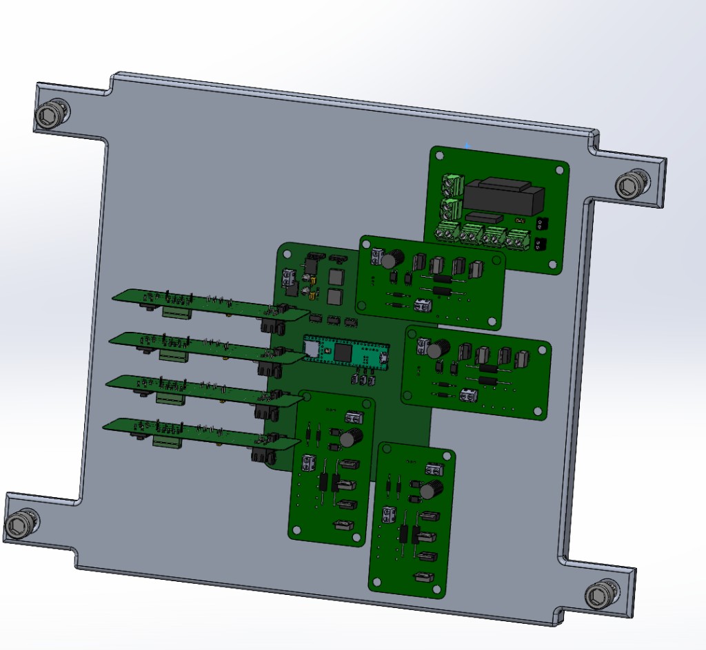
Assembled Electrical System
All the PCBs were mounted vertically inside the base to save space and reduce the motherboard footprint. Below is a SolidWorks render of the full electronics stack: the Teensy on the motherboard, four identical motor driver boards, encoder boards, and the power supply section, all mounted to a common back plate with corner standoffs.
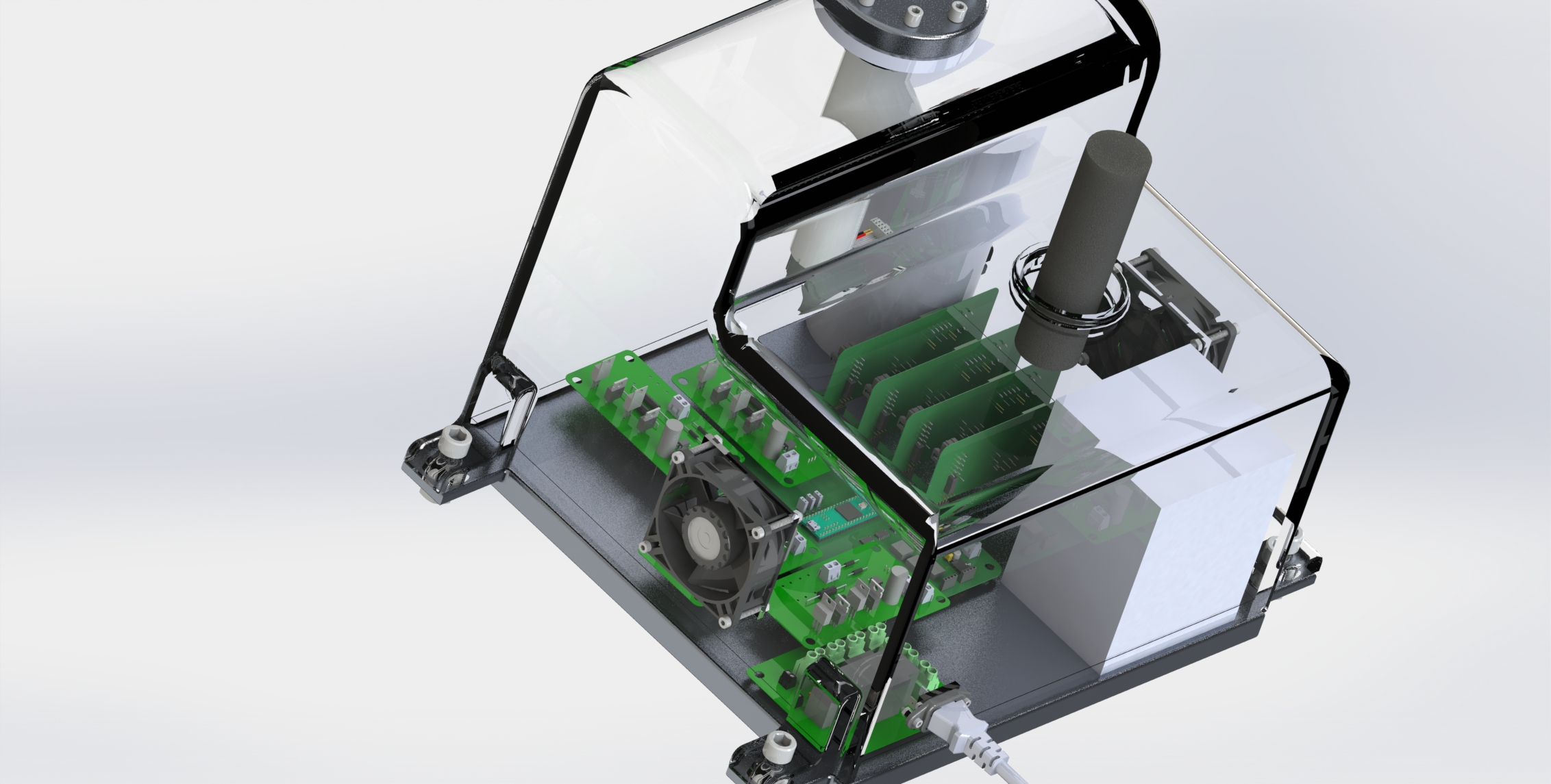
Here is a photo of the assembled boards housed inside the robot base:
Software and Control System
PID Controller Design
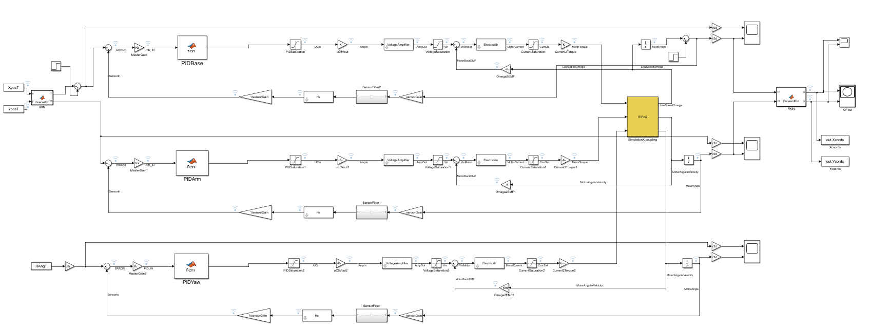
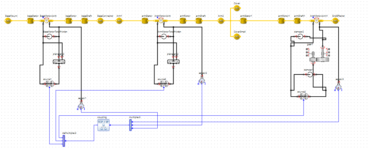
The control system was first designed and tuned in MATLAB/Simulink before being translated to C code for the Teensy. Each motor has its own PID loop running at 1000 Hz. The system model chains together the voltage amplifier transfer function (derived from a SPICE simulation), the motor electrical model, current and voltage saturation blocks, and the mechanical load model (G(s) = 1/(Js + B)).
Tuning happened in two phases. The first was an analytical process in Simulink: computing phase margins, placing zeros and poles relative to the phase crossover frequency, and iterating until the response stabilized. The second was heuristic tuning after connecting the Simulink controller to the SimulationX mechanical model via cosimulation, adjusting gains while observing the physical behavior.
The final PID gains (as configured in C code) were:
Base (Shoulder): Kp = 1500, Ki = 200, Kd = 280
Arm (Elbow): Kp = 1250, Ki = 150, Kd = 50
Yaw: Kp = 40, Ki = 6.1, Kd = 3.4
Kinematics
Forward and inverse kinematics convert between XY coordinates and joint angles using the cosine law. With the upper arm at 300mm and the forearm at 150mm, the maximum reach is 450mm from the shoulder.
Inverse Kinematics (given X, Y coordinates, compute joint angles): the distance from base to target is first computed as L3 = sqrt(X² + Y²). Then atan2 and the cosine law are used to solve for the shoulder angle and elbow angle.
Forward Kinematics (given joint angles, compute X, Y coordinates): the end of the upper arm position is computed from the shoulder angle, and then the forearm vector is added using the combined shoulder plus elbow angle.
Path Planning
The path planner generates a sequence of XY waypoints for the PID controller to follow. It accepts start and end coordinates along with a total travel time, then linearly interpolates the positions at 500 Hz (a new target position every 2ms). The planner handles both Cartesian and polar coordinate inputs, converting polar to Cartesian internally.
Homing Sequence
On startup, the robot runs a homing sequence where each arm slowly rotates until it contacts a limit switch (mechanical stopper). The known angle at that contact point, computed from the SolidWorks CAD model using triangle geometry, is then sent to the encoder board over I2C to calibrate the absolute position. The calibrated reference angles are 30° for the upper arm and 120° for the forearm.
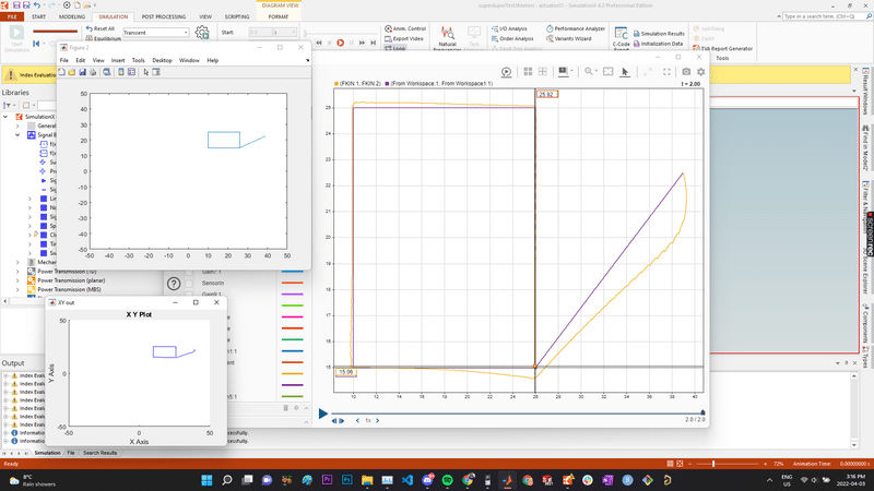
Simulation and Testing
The simulation environment combined Simulink (for the control system) and SimulationX (for the mechanical dynamics) running as a cosimulation. The SolidWorks CAD models were imported into SimulationX with accurate masses, centers of mass, and inertia tensors. Motor friction was modeled as B = NoLoadTorque / NoLoadSpeed, and gearbox friction was approximated by scaling motor friction by the gear ratio.
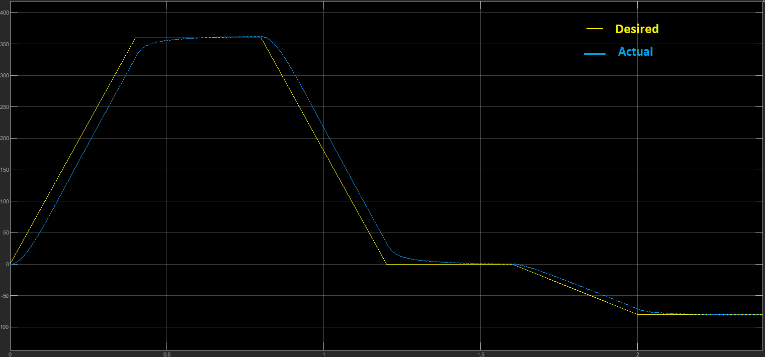
Square Path Test
The robot was commanded to trace a rectangular path while carrying a 3 kg payload. It completed the path in under 2 seconds, comfortably meeting the cycle time requirement of less than 5 seconds.
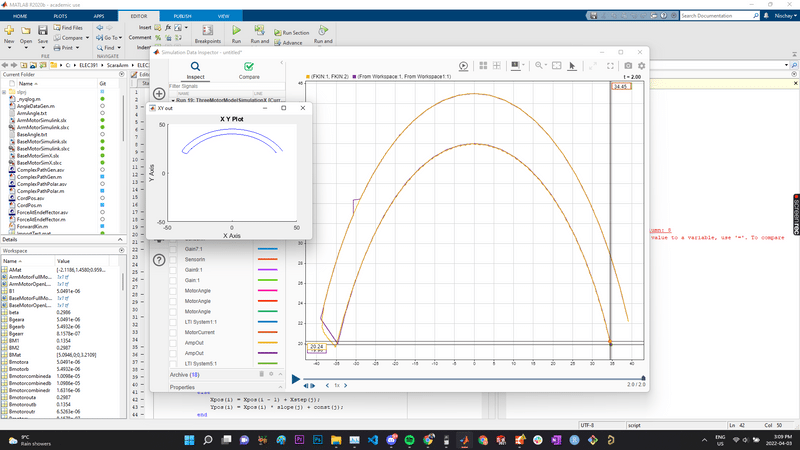
Half Circle Test
This test verified the robot’s ability to follow curved paths and confirmed that both joints exceed their minimum rotation angle requirements (upper arm > ±50°, forearm > ±60°).

End Effector Tests
The end effector’s rotation and linear motion were also tested independently.
Rotation Test:
Vacuum Pickup Mechanism (picking up and releasing objects):
Robustness Test
A bearing wear simulation (10x normal friction at the elbow joint) showed that the robot still operated with reasonable accuracy despite significant delay and undershoot, demonstrating the system’s robustness to mechanical degradation.
Cost and Tradeoffs
The total estimated cost of the robot was approximately $4,050 CAD, broken down as follows:
- Maxon motors: ~$2,900
- Motherboard and electronics: ~$500
- Structural parts (material + manufacturing): ~$600
- Hardware (screws, nuts, fasteners): ~$50
Key design tradeoffs we made along the way:
- Base size: We had to enlarge the base from the original Yamaha dimensions to 350mm x 350mm x 300mm because we housed the transformer internally, whereas the Yamaha model keeps it external.
- Upper arm length: Extended from 200mm to 300mm. The shorter arm gave too small of a pickup range relative to the enlarged base.
- Forearm material: Switched from Aluminium Alloy 3003 to ABS Plastic because the aluminium version was too heavy for the elbow motor to drive effectively.
Reflections
This project was one of the most rewarding experiences of undergrad. It brought together mechanical design, electronics, control theory, and software engineering into a single cohesive system. Designing four custom PCBs, tuning PID controllers in MATLAB, and watching the robot arm trace a path in cosimulation for the first time was incredibly satisfying.
Thank you for reading! If you have any questions about the project, feel free to ask them in the comments below.